Projected Virtual Board
Write on any surface with an LED pen
A Project By Jiachao Chen(jc3345), Yuqing Shou(ys895).
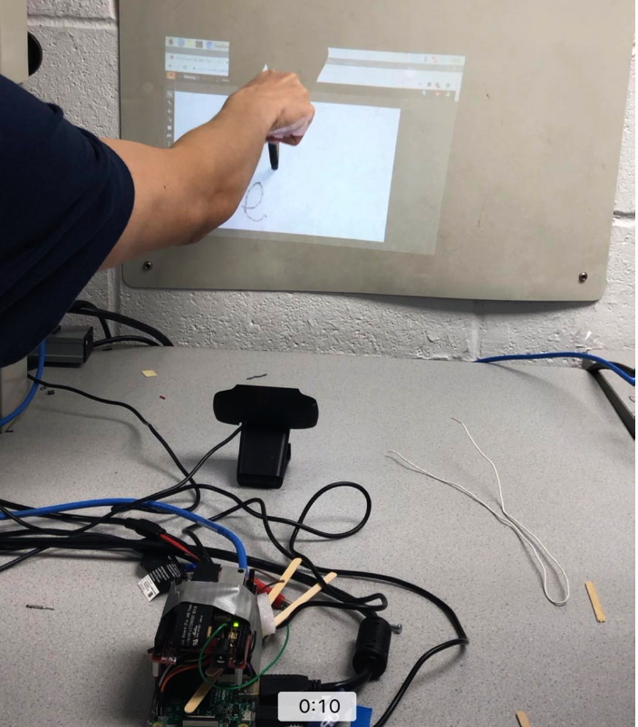
Demonstration Video
Introduction
Nowadays, many people need boards and pens to write down important notes on the board to share the essential information to everyone during a meeting or lecture. However, the physical boards and pens are not convenient to be carried, because they are either too heavy or too large. As a result, this project provide a solution to solve this problem by utilizing Texas Instrument DLP Light Crafter Display board, Raspberry Pi and a camera to build to a small, light and portable virtual board device that can project a virtual board on the wall and users can use the LED pen to write down anything on the board.
Project Objective
There are several goals in the project:
- Computed the perspective transformation matrix by OpenCV and then apply it to the Raspberry Pi.
- Implemented Power Law Transformation to enhance the display of the projected virtual board.
- Recognized the red color of the LED pen light by image thresholding.
- Utilized the LED pen to control the mouse by finding the red light’s contour area and moments.
Hardware Components
There are four basic hardware components in the project
- Raspberry Pi.
- DLPDLCR2000EVM DLP LightCrafter.
- Logitech C920 HD Pro Webcam.
- LED Pen
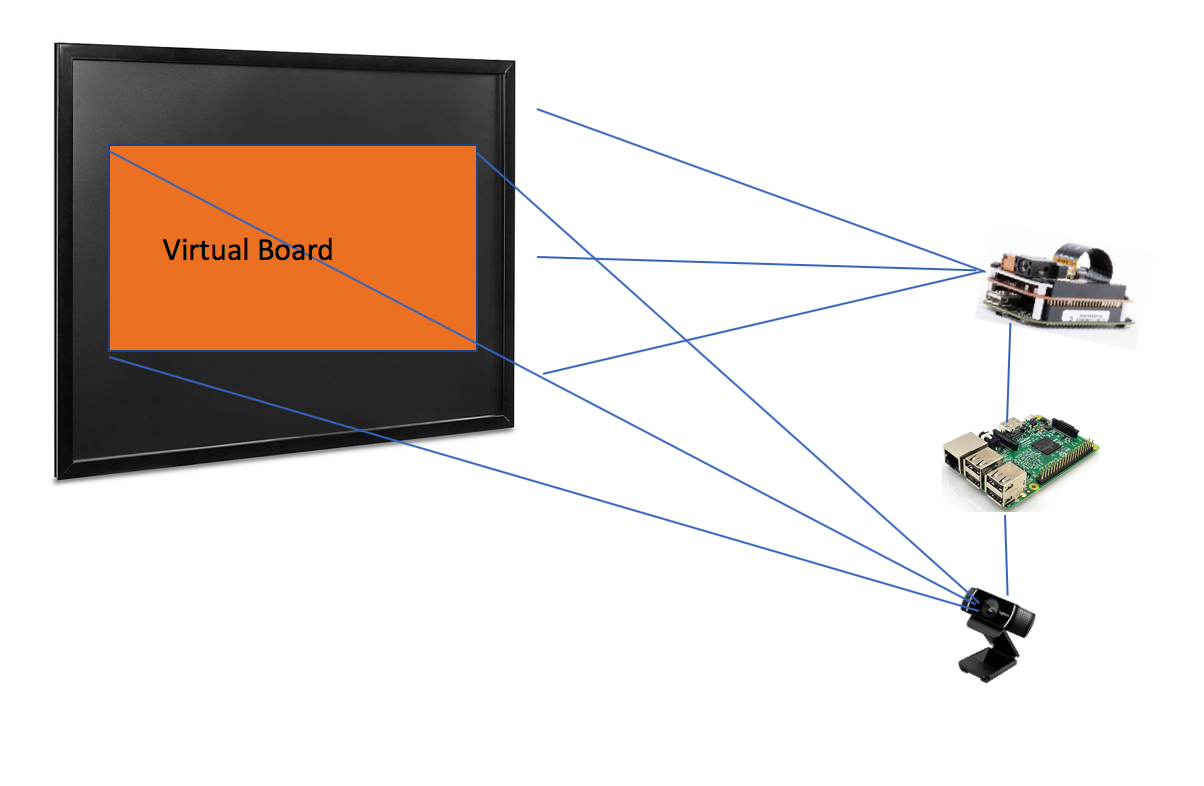
Raspberry Pi will be the main component in this project, because it will carry the main program to implement all the functions of the virtual board. Moreover, the virtual board will be projected by the DLPDLCR2000EVM DLP LightCrafter on a wall, and DLPDLCR2000EVM DLP LightCrafter is connected with Raspberry Pi.
In addition, the Camera will be utilized by the Raspberry Pi, and it will capture and recognize the projected virtual board to send the parameters including length and width of the virtual board and also will the distance between DLPDLCR2000EVM DLP LightCrafter and board.
Furthermore, the Digital Pen will have an LED light (or some light is brighter than the LED) on the head of the pen, and it will also have a switch that turns on and turns off the LED. In addition, the Digital Pen will also have a battery that is attached in the tail of the pen to provide the power of the Digital Pen. In a further step, the digital may have more switches to provide additional functions such as select and hold. However, at the first stage of the project, it will only provide the function of writing for the project.
The basic installation is shown below:
Design
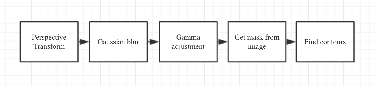
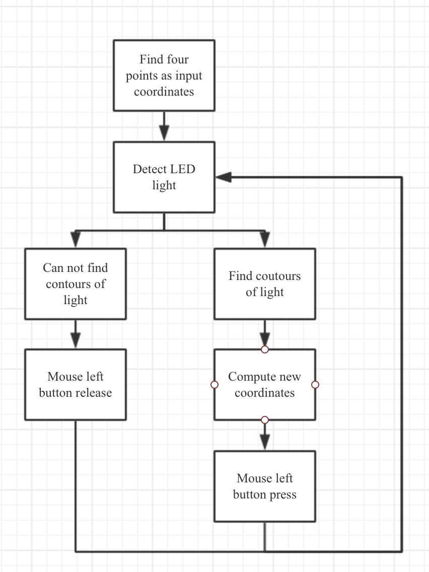
Although with the limitation of computation, our algorithm of LED light detection runs on the Raspberry Pi with reduced resolution in order to reduce the computation. We set the OpenCV window size to 640x640 and the process image size to 370x640, which is a reasonable resolution that we successfully tested on the Raspberry Pi. The window size is the first window that appears for us to find first four points as input coordinates and the process image size is the size of the image that the following computer vision algorithm runs with. We set the lower bound and upper bound of the color to (160, 100, 200) and (179, 255, 255) in the HSV. It is able to detect most of red light from LED pen. During the test, we solve several problems: 1. The LED light should be strong and big enough to be captured by the camera, which means that the LED pen's light influence our project performance. 2. The computation of our algorithm and the real-time performance of our project is a trade-off, higher resolution means more accurate result but more lagging while writing or drawing. All the image processing steps are implemented through opencv. And mouse movements and operations are imitated through pyautogui. The workflow of our algorithm is in the workflow chart.
Result
We test our software and hardware components in the class lab, adjust light of the room in order to imitate the real situations in the classroom.
Possible Improvement
There are several aspects of improvements in the software and hardware that we thought about after the project is over.
- As in this project, we are using LED pen with a little difficulty of writing and painting on a projected surface, we can instead use a laser pen as most classrooms have them and in order to achieve this, a better algorithm is needed to capture the small laser dot that shows on the projected surface.
- The algorithm can be optimized by reducing the computation or we can move the computation to the cloud, every time the cloud finished the computation it sends the result to the Raspberry Pi.
- The software part can be optimized to limit the space in the screen that can be used for drawing due to that not full screen is needed for writing and painting.
Work Distribution
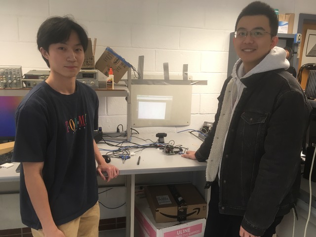
Project group picture

Jiachao Chen
jc3345@cornell.edu
Yuqing Shou
ys895@cornell.edu
Parts List
- Raspberry Pi $35.00
- LPDLCR2000EVM DLP LightCrafter $90.00
- LEDs, Resistors and Wires - Provided in lab
Total: $125
Code Appendix
// Writer.py
# 11/30/2019
# ECE5725 Final Project
# Yuqing Shou(ys895), Jiachao Chen(jc3345)
import cv2
import numpy as np
import pyautogui
from pynput.mouse import Button, Controller
import time

class Writer:
    def __init__(self, mouse, alpha = 2, gamma = 0.5, points = [(0,0),(0,0),(0,0),(0,0)], flag = False, prc_img_size = (740/2,1280/2), lower = (160, 100, 200), upper = (179, 255, 255), points_cnt = 0):
        '''
        Writer object
        :param mouse: mouse object
        :param alpha: value of alpha
        :param gamma:  value of gamma
        :param points: coordinates of the image on the opencv windows
        :param flag: initial flag
        :param prc_img_size:  process image size
        :param lower: lower bound of the color
        :param upper: upper bound of the color
        :param points_cnt: counter of points
        '''
        self.cap = cv2.VideoCapture(0)
        self.cap.set(3,640)
        self.cap.set(4,640)
        _,self.img = self.cap.read()
        self.alpha = alpha
        self.mouse = mouse
        self.points = points
        self.gamma = gamma
        self.flag = flag
        self.prc_img_size = prc_img_size
        self.upper = upper
        self.lower = lower
        self.out_points = np.float32([[0,0],[prc_img_size[1],0],[0,prc_img_size[0]],[prc_img_size[1],prc_img_size[0]]])
        self.points_cnt = points_cnt

    # gamma transformation
    def gamma_adjustment(self, image, gamma):
        '''
        adjust the gamma value of an image
        :param image: input image
        :param gamma: value of gamma
        :return: new image
        '''
        invGamma = 1.0 / gamma
        table = np.array([((i / 255.0) ** invGamma) * 255
            for i in np.arange(0, 256)]).astype("uint8")
        # LUT transform
        return cv2.LUT(image, table)

    # record the coordinates of the points in the window
    def draw_points(self,event,x,y,flags,param):
        '''
        call-back function to draw points on the opencv window
        :param event: event
        :param x: x
        :param y: y
        :param flags: flags
        :param param: param
        :return: none
        '''
        if event == cv2.EVENT_LBUTTONDOWN:
                cv2.circle(self.img,(x,y),5,(0,255,0),-1)
                self.points[self.points_cnt] = (x,y)
                #print(pointIndex)
                self.points_cnt = self.points_cnt + 1

    def window_points(self):
        '''
        find four points on the opencv window
        :return: none
        '''
        while True:
                #print(pts,pointIndex-1)
                cv2.imshow('img', self.img)

                if(self.points_cnt == 4):
                    print(self.points)
                    break

                if (cv2.waitKey(20) & 0xFF == 27) :
                    break

    # perspective transformation
    def perspetive_transform(self, image,points):
        '''
        standard opencv perspective transformation: same object's position in different coordinates
        :param image: input image
        :param points: input coordinates of an image
        :return: new image
        '''
        in_points = np.float32(points)
        Map = cv2.getPerspectiveTransform(in_points,self.out_points)
        warped = cv2.warpPerspective(image, Map, (self.prc_img_size[1], self.prc_img_size[0]))
        return warped

    def write(self):
        '''
        main function used for writer
        :return: none
        '''
        cv2.namedWindow('img')
        # mouse callback functions
        cv2.setMouseCallback('img',self.draw_points)
        print('Please points at: Top Left, Top Right, Bottom Left, Bottom Right')

        # constantly show the image img unless there are four points detected
        self.window_points()
        #cv2.destroyAllWindows()

        while True:
            # capture the frame by the camera
            _, frame = self.cap.read()
            warped = self.perspetive_transform(frame, self.points)

            blurred = cv2.GaussianBlur(warped, (9, 9), 0)

            adjusted = self.gamma_adjustment(blurred, self.gamma)

            hsv = cv2.cvtColor(adjusted,cv2.COLOR_BGR2HSV)
            mask = cv2.inRange(hsv, self.lower, self.upper)

            # ret & otsu
            ret, otsu = cv2.threshold(mask,0,255,cv2.THRESH_BINARY+cv2.THRESH_OTSU)

            # find contours from the previous image
            contour_num = cv2.findContours(otsu.copy(), cv2.RETR_EXTERNAL,
                cv2.CHAIN_APPROX_SIMPLE)[-2]
            center = None

            a = 0
            b = 0
            # only proceed if at least one contour was found
            if len(contour_num) > 0:
                # find the largest contour in the mask, then use
                # it to compute the minimum enclosing circle and
                # centroid
                c = max(contour_num, key=cv2.contourArea)
                ((x, y), radius) = cv2.minEnclosingCircle(c)
                a = x
                b = y
                print("a:" + str(b) + ", b:" + str(b))
                M = cv2.moments(c)
                if M["m00"] != 0:
                    center = (int(M["m10"] / M["m00"]), int(M["m01"] / M["m00"]))
                else :
                    center = (0,0)

                # only proceed if the radius meets a minimum size
                if (radius>1):
                    self.flag = True
                    print(radius)
                    # draw the circle and centroid on the frame,
                    # then update the list of tracked points
                    cv2.circle(frame, (int(x), int(y)), int(radius),
                        (0, 255, 255), 2)

                    cv2.circle(frame, center, 5, (0, 0, 255), -1)

            width, height = pyautogui.size()

            m = (a/1280)*100
            n = (b/740)*100

            # coordinates in the screen
            k = (width*m)/100
            c = (height*n)/100

            #pyautogui.FAILSAFE = False
            #pyautogui.moveTo(k,c)

            if self.flag == True :
                self.mouse.position = (int(k), int(c))
                print(int(k),int(c))
                self.mouse.press(Button.left)

            else:
                self.mouse.release(Button.left)

            self.flag = False

            cv2.imshow('mask', mask)
            cv2.imshow('warped',warped)
            #cv2.imshow('blurred', blurred)
            #cv2.imshow('hsv', hsv)
            #cv2.imshow('frame',frame)
            #cv2.imshow('dilate',dilate)


            k=cv2.waitKey(5) & 0xFF
            if k == 27:
                break

        self.cap.release()

# main function
if __name__ == "__main__":
    mouse = Controller()
    writer = Writer(mouse)
    writer.write()
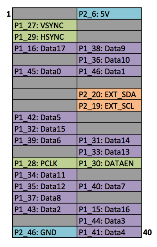
Raspberry Pi: /boot/config.txt configuration
                # Add support for software i2c on gpio pins
                dtoverlay=i2c-gpio,i2c_gpio_sda=23,i2c_gpio_scl=24,i2c_gpio_delay_us=2

                # DPI Video Setup
                dtoverlay=dpi18
                overscan_left=0
                overscan_right=0
                overscan_top=0
                overscan_bottom=0
                framebuffer_width=854
                framebuffer_height=480
                enable_dpi_lcd=1
                display_default_lcd=1
                dpi_group=2
                dpi_mode=87

                dpi_output_format=458773
                hdmi_timings=854 0 14 4 12 480 0 2 3 9 0 0 0 60 0 32000000 3
Raspberry Pi Wiring